Operation of an active filter in a DC charging station
The plan and main idea of this material is as follows. To begin with, let’s figure out what harmonics are and why having harmonics in the network is bad. Then we will find out how, generally, they can be fought and how effective such a struggle can be. In the following, we will show why it is worth paying attention to parasitic harmonics when operating a DC charging station. And finally, let’s consider the operation of an active harmonic filter as a separate device, and as part of a DC charging station.
Harmonics are currents with a frequency that is a multiple of the fundamental frequency (most often it is 50 Hz) and differs from it by several times. It is customary to consider harmonics with a frequency of 100 Hz as harmonics of the second order, 150 Hz – the third order, 200 Hz – the fourth, etc.
Harmonics are superimposed on the main frequency current and distort its shape. It is known that the ideal current has the form of a sinusoid, the same can be said about the voltage in the AC network. In this case, all the electricity that is transmitted through the network is converted into useful work. If we are dealing with a distorted form of the electrical parameters of the network, then the efficiency of the electrical machines is reduced.
The figure below shows how the harmonics add up to form the resulting irregularly shaped curve.
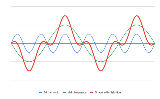
Harmonic distortion
Harmonic sources are non-linear loads, most often these are computer power supplies, control elements of energy-saving light sources, rectifiers and inverters, various asynchronous electric motors with frequency drive, etc.
The better the equipment (load) that consumes electricity in terms of regulation, power consumption, functionality, the more harmonics it generates in the power grid and the more significantly the main network parameters are distorted – current, voltage, frequency, combined in the concept of power quality.
The negative consequences of the action of harmonics include:
- Overheating of distribution equipment (cables, transformers, generators, etc.).
- Overvoltages and circulating currents arising from the resonance of harmonics.
- Unpredictable operation of protective devices.
- Reducing the power factor of electrical systems.
So, harmonics need to be dealt with. And there are means for such a struggle. One such tool is the passive filter, which combines capacitive and inductive loads that resonate with and cancel unwanted harmonics.
Passive filters successfully cope with harmonics up to 11-13 orders. They are inexpensive, simple, and do not require special maintenance. The passive filter is adjusted so that at the frequency of the harmonic to be neutralized, it has a small resistance, so it would be easier for the current to go through the filter, and there the harmonic energy is dissipated in the wires, connections and wasted on heating.
In addition to passive filters, there are active harmonic filters that work to detect harmonics up to the fiftieth order in the system. An active filter has a completely different principle of operation – it analyzes the detected harmonics and generates currents of the same frequency and amplitude, but in antiphase. Thus, it compensates for harmful harmonics of any order. The faster the filter works, the cleaner the network becomes.
Active filters are used in charging stations to eliminate the influence of the generated harmonics on the network parameters.
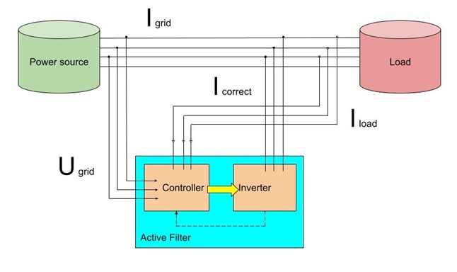
Active filter diagram
Beside harmonic distortion, there is also such a phenomenon as a phase shift between voltage and current with a reactive load. If, for example, the load is an induction motor, then the current usually lags the voltage in phase. The greater the load, the greater the lag. In this case, the waveform of the current and voltage is not distorted, but the energy efficiency of the system is also reduced. Then a passive filter is good, which simply connects a capacitance in parallel to the network, compensating for the phase shift of the capacitive component. The active filter in this case is somewhat inferior in efficiency, but also performs this function. But in terms of harmonic compensation, an active filter clearly has an advantage.
Since the active filter can correct not only harmonics, but also phase difference (Cos Fi), it can be used in other devices, in particular, those designed for reactive power compensation. The operation of the active filter in such devices is very effective.
If passive filters mainly generate compensating currents of a capacitive nature, then an active filter generates both capacitive and inductive currents, significantly improving the quality of network parameter correction.
Mention should also be made of intermodulation distortion (stray currents that are not multiples of the fundamental frequency). They cause beats when superimposing amplitudes due to the sum or difference of the fundamental and harmonic frequencies. This can lead to resonances and, as a result, to heating of the lines, or overvoltages in the network. Such problems occur when the load is a collection of devices operating independently and out of sync. In charging stations, this may be the case with several power units operating on one or more outputs. Since the operation of the active filter is based on the analysis of instantaneous network parameters using high-speed sensors, it also copes with these problems perfectly.
Two connection schemes are used – serial and parallel.
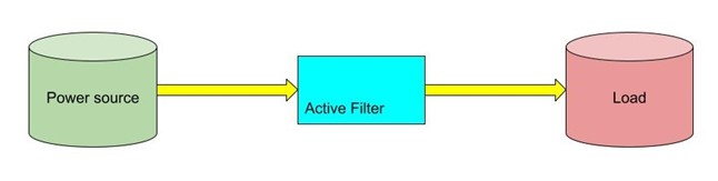
Serial connection
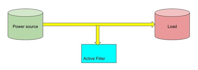
Parallel connection
The first scheme implies better work, but entails high costs. In it, the filter power cannot be less than the load power. In the second case, a filter with a power of approximately 40% of the load power is usually sufficient.
Both connection diagrams apply to both active and passive filters. Both of these schemes are designed to increase the useful power factor PF. When connected in series, the filters are focused on suppressing harmonics, bringing the current shape to a sinusoid, and when connected in parallel, they are aimed at compensating for the shift between current and voltage.
Also of great importance is the place where the filter is located. The closer it is to the place where harmonics are generated, the more effectively it fights them. That is why in charging stations the filter and the power unit are structurally combined or are located very close.
The obvious advantages of the active filter include its weight and dimensions. It takes up significantly less space in the electrical system, it is easy to mount and move.
If we compare which type of filter to choose to improve the quality of the power supply, then you need to have an idea of the load. If the load is inductive (induction motors, pumps, drives), the shape of the sinusoid is slightly distorted, then the power factor will be determined only by Cos Fi, then PF = Cos Fi and a passive filter is quite suitable. No wide range of harmonics will need to be compensated, only reactive power compensation. Using the formula for calculating the net power factor PF = Cos Fi / SQR(1 + THD^2), we see that it depends on the harmonic distortion factor THD.
In a DC charging station, the load is caused precisely by SMPS devices, which include switching power supplies, power rectifiers, double conversion devices with a DC link, and inverters. In the charging station there is a wide range of harmonics in the network and then, the power factor PF, along with the phase shift, will also be determined by the harmonic distortion factor THD. In this case, THD will be decisive. In this case, the passive filter will be ineffective, since it does not deal well with harmonics, and reactive power compensation is almost not required. In this case, it is the active filter that will fully manifest itself, since it fights harmonics very well.